- 您现在的位置:买卖IC网 > Sheet目录3875 > PIC16F628A-I/P (Microchip Technology)IC MCU FLASH 2KX14 EEPROM 18DIP
PIC16F627A/628A/648A
DS40044G-page 108
2009 Microchip Technology Inc.
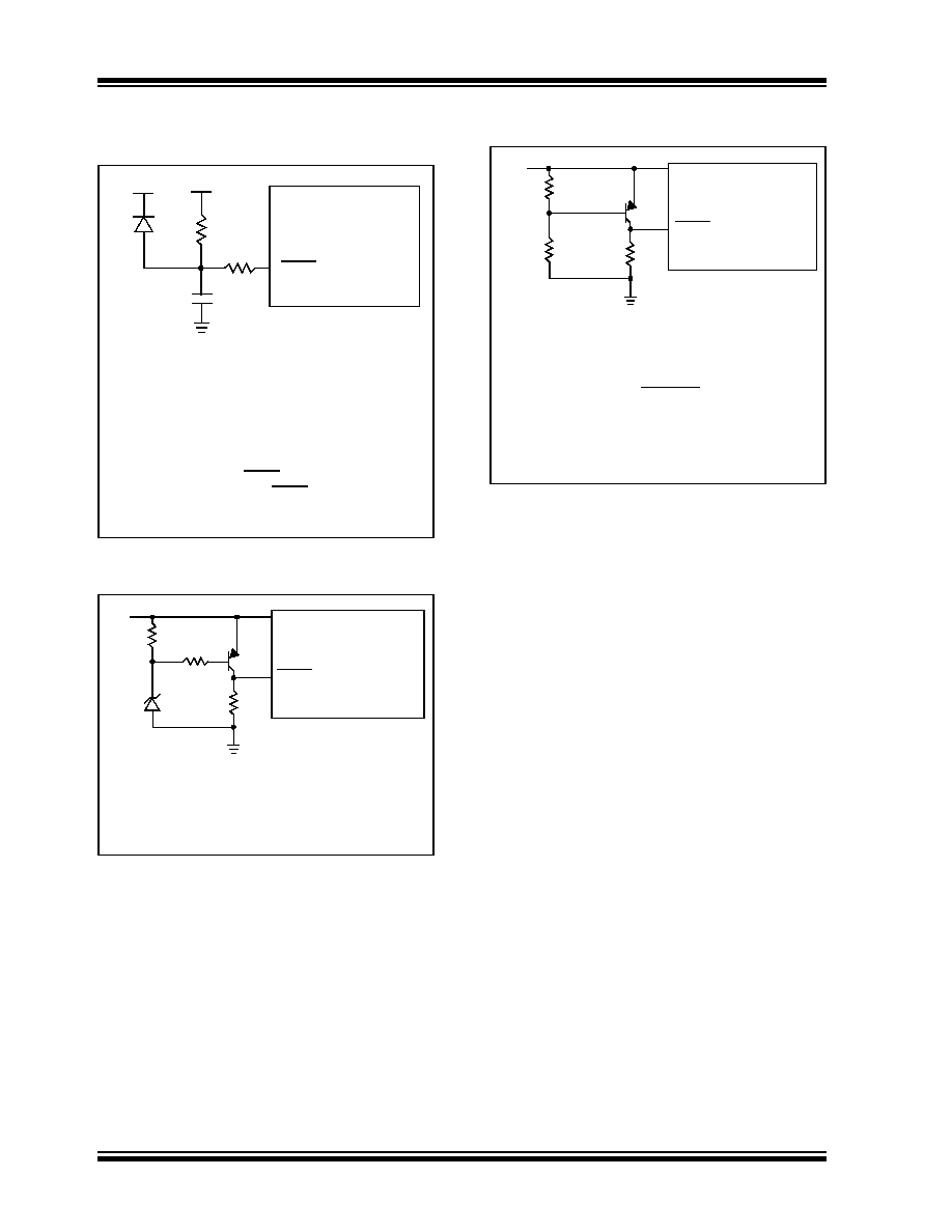
FIGURE 14-11:
EXTERNAL POWER-ON
RESET CIRCUIT (FOR
SLOW VDD POWER-UP)
FIGURE 14-12:
EXTERNAL BROWN-OUT
PROTECTION CIRCUIT 1
FIGURE 14-13:
EXTERNAL BROWN-OUT
PROTECTION CIRCUIT 2
Note
1:
External Power-on Reset circuit is required
only if VDD power-up slope is too slow. The
diode D helps discharge the capacitor
quickly when VDD powers down.
2:
R < 40 k
Ω is recommended to make sure
that voltage drop across R does not violate
the device’s electrical specification.
3:
R1 = 100
Ω to 1 kΩ will limit any current
flowing into MCLR from external capacitor
C in the event of MCLR/VPP pin break-
down due to Electrostatic Discharge (ESD)
or Electrical Overstress (EOS).
C
R1
R
D
VDD
MCLR
PIC16F627A/628A/648A
VDD
Note
1:
This circuit will activate Reset when VDD
goes below (Vz + 0.7V) where Vz = Zener
voltage.
2:
Internal Brown-out Reset circuitry should
be disabled when using this circuit.
VDD
33k
10k
40k
VDD
MCLR
PIC16F627A/628A/648A
x
R1
R1 + R2
= 0.7 V
VDD
R2
40k
VDD
MCLR
PIC16F627A/628A/648A
R1
Q1
Note
1:
This brown-out circuit is less expensive,
albeit less accurate. Transistor Q1 turns off
when VDD is below a certain level such that:
2:
Internal Brown-out Reset should be
disabled when using this circuit.
3:
Resistors should be adjusted for the
characteristics of the transistor.
VDD x
R1
R1 + R2
= 0.7 V
发布紧急采购,3分钟左右您将得到回复。
相关PDF资料
PIC18F24K22-I/SO
IC PIC MCU 16KB FLASH 28SOIC
PIC18F23K22-I/SP
IC PIC MCU 8KB FLASH 28SPDIP
PIC18LF23K22-I/SP
IC PIC MCU 8KB FLASH 28SPDIP
PIC24F08KA102-I/SS
IC PIC MCU FLASH 8K 28-SSOP
PIC16C58B-20/SO
IC MCU OTP 2KX12 18SOIC
PIC12C672-04/SM
IC MCU OTP 2KX14 A/D 8-SOIJ
PIC18F25K20-E/SS
IC PIC MCU FLASH 16KX16 28-SSOP
PIC18F25J10T-I/SO
IC PIC MCU FLASH 16KX16 28SOIC
相关代理商/技术参数
PIC16F628A-I/P
制造商:Microchip Technology Inc 功能描述:IC 8BIT FLASH MCU 16F628 DIP18
PIC16F628A-I/SO
功能描述:8位微控制器 -MCU 3.5KB 224 RAM 16 I/O RoHS:否 制造商:Silicon Labs 核心:8051 处理器系列:C8051F39x 数据总线宽度:8 bit 最大时钟频率:50 MHz 程序存储器大小:16 KB 数据 RAM 大小:1 KB 片上 ADC:Yes 工作电源电压:1.8 V to 3.6 V 工作温度范围:- 40 C to + 105 C 封装 / 箱体:QFN-20 安装风格:SMD/SMT
PIC16F628A-I/SO
制造商:Microchip Technology Inc 功能描述:8BIT FLASH MCU SMD 16F628 SOIC18
PIC16F628A-I/SOG
制造商:Microchip Technology 功能描述:MCU 8-Bit PIC16 PIC RISC 3.5KB Flash 3.3V/5V 18-Pin SOIC W Tube
PIC16F628A-I/SS
功能描述:8位微控制器 -MCU 3.5KB 224 RAM 16 I/O RoHS:否 制造商:Silicon Labs 核心:8051 处理器系列:C8051F39x 数据总线宽度:8 bit 最大时钟频率:50 MHz 程序存储器大小:16 KB 数据 RAM 大小:1 KB 片上 ADC:Yes 工作电源电压:1.8 V to 3.6 V 工作温度范围:- 40 C to + 105 C 封装 / 箱体:QFN-20 安装风格:SMD/SMT
PIC16F628A-I/SS
制造商:Microchip Technology Inc 功能描述:8BIT FLASH MCU SMD 16F628 SSOP20
PIC16F628AT-E/ML
功能描述:8位微控制器 -MCU 28LD 20MHz 2K FLASH RoHS:否 制造商:Silicon Labs 核心:8051 处理器系列:C8051F39x 数据总线宽度:8 bit 最大时钟频率:50 MHz 程序存储器大小:16 KB 数据 RAM 大小:1 KB 片上 ADC:Yes 工作电源电压:1.8 V to 3.6 V 工作温度范围:- 40 C to + 105 C 封装 / 箱体:QFN-20 安装风格:SMD/SMT
PIC16F628AT-E/SO
功能描述:8位微控制器 -MCU 18LD 20MHz 2K FLASH RoHS:否 制造商:Silicon Labs 核心:8051 处理器系列:C8051F39x 数据总线宽度:8 bit 最大时钟频率:50 MHz 程序存储器大小:16 KB 数据 RAM 大小:1 KB 片上 ADC:Yes 工作电源电压:1.8 V to 3.6 V 工作温度范围:- 40 C to + 105 C 封装 / 箱体:QFN-20 安装风格:SMD/SMT